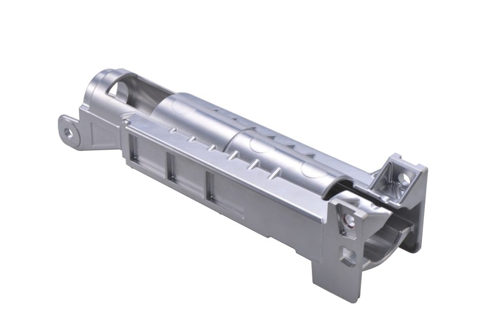
Thin-wall CNC machining requires the finished design and the manufacturing sequence to be considered together. A housing may be sufficiently stiff after assembly, yet still deflect while material is removed or while the part is held for machining and inspection. Early discussion of the functional envelope can reveal practical changes before the design is frozen.
Wall stiffness affects the machining route
Cutting forces and clamping pressure can move a thin section away from its nominal position. Unsupported height, pocket depth, surrounding ribs and transitions between thick and thin areas all influence how the component behaves during machining.
Instead of selecting wall thickness in isolation, review the full load path through the housing. Ribs, flanges and local bosses may add stiffness where the design allows them. Gradual transitions can also be easier to plan than abrupt changes in section.
Review tool access, depth and corner geometry together
Deep pockets and narrow gaps may require longer cutting tools. Longer reach can reduce tool stiffness and affect the choice of cutting strategy. Internal corners also follow the geometry of the cutting tool, so very small corner radii in deep areas may add difficulty without improving the part’s function.
Review pocket depth, corner radii, nearby walls and access direction as one system. If a feature can be reached from more than one orientation, the setup plan and datum relationships should be considered before deciding whether an additional axis or repositioning step is appropriate.
Choose datums that remain useful during inspection
Identify stable surfaces that can locate the component during machining and measurement. Explain which interfaces control assembly and which dimensions relate to those interfaces. A datum scheme that reflects part function helps align the drawing, workholding plan and inspection report.
Flexible features may produce different readings in a free state and in an assembly fixture. If the acceptance condition matters, define it on the drawing rather than leaving the supplier and customer to use different measurement assumptions.
Consider material condition and finishing
Material condition, residual stress and the sequence of material removal can affect a lightweight component. Surface treatment may also introduce masking, contact or cosmetic requirements. State the required material and finish, and identify surfaces whose appearance or fit must be protected.
There is no universal wall-thickness value that applies to every CNC-machined housing. The practical approach depends on material, geometry, unsupported length, tolerances, quantity and the proposed process. Numerical limits should therefore be reviewed for the actual part.
Thin-wall housing design review checklist
- Highlight functional walls, ribs and assembly interfaces
- Identify deep pockets and restricted tool access
- Use internal radii that match the functional need
- Define stable datums and the inspection condition
- Separate critical tolerances from general dimensions
- Specify material condition, finish and cosmetic surfaces
- Share prototype and expected batch quantities
See an example part family in our thin-wall CNC housings section, or review our 5-axis CNC machining capability. For a part-specific discussion, send the current model and drawing.
Further reading: Protolabs Network: designing parts for CNC machining.