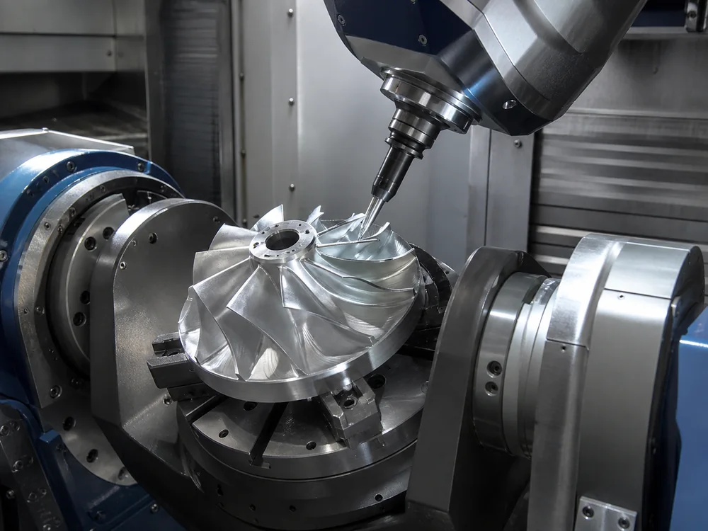
Multi-face CNC machining becomes challenging when features on different surfaces must maintain a defined relationship. A bore, mounting face or angled hole may be straightforward on its own, while their combined position and orientation make the manufacturing and inspection plan more demanding.
Part complexity comes from feature relationships
Begin by identifying the interfaces that locate the component in its assembly. A drawing should show which faces act as datums and which bores, holes or surfaces are controlled from them. This allows the supplier to distinguish functional relationships from general geometry.
When requirements are spread across several drawing views, add notes or a short explanation of the assembly function. The intention is not to tell the supplier how to machine the part, but to make the acceptance criteria unambiguous.
Tool access influences the process sequence
Additional machine axes provide more ways to orient the tool relative to the workpiece. Depending on the geometry, this can improve access to angled or contoured features and may reduce the need to reposition the part. It does not remove the need for suitable workholding, clear datums or an inspection plan.
The manufacturing route may use several orientations or setups. The relevant question is how the chosen sequence controls relationships between critical features while providing safe tool and fixture access.
Workholding must protect functional surfaces
A fixture must locate the part consistently without obstructing the features being machined. Thin walls, finished faces and restricted clamping areas can limit the available choices. If a surface cannot be used for holding or contact, identify that restriction in the RFQ.
Prototype and repeat-batch quantities may justify different fixture strategies. Sharing the expected quantity helps the supplier review the balance between setup effort, repeatability and production flexibility.
Datums connect machining with inspection
The datum structure should support both manufacturing and verification of the final component. Critical feature relationships may require measurements across multiple faces, so the drawing should define the origin and orientation used for acceptance.
List required reports or approval steps before quotation. The inspection plan can then be reviewed alongside the machining route rather than added after the part has been produced.
Information to include in a multi-face part RFQ
- Current 3D model and dimensioned drawing
- Functional datums and mating interfaces
- Critical bore, hole and surface relationships
- Restrictions on clamping or surface contact
- Material, heat treatment and surface finish
- Prototype and anticipated repeat quantity
- Inspection reports and documentation requirements
Explore our multi-face CNC housings and 5-axis CNC machining pages for related examples. For a drawing-specific review, send the model, drawing and quantity.
Further reading: Autodesk: five-axis machining.